Building a Stable Power Foundation for Automotive Electronics
In electronics, ensuring a stable and reliable power supply is paramount. In automotive electronics a robust voltage regulation system is even more critical as we deal with line noise and power fluctuation. In this article, we demystify the topic of voltage regulation. In the process we’ll demonstrate how to build a stable 5V power supply using the LM317 voltage regulator.
Understanding Voltage Regulators:
Voltage regulators are devices that maintain a constant output voltage in spite of fluctuation in input voltage or load conditions. The circuits to accomplish this are complicated, but luckily we can buy integrated circuits (ICs) that do most of the work for us. The LM317, for example, has 29 active transistors contained in a small package. Now lets take a closer look at the LM317.
The LM317 Voltage Regulator
One of the most versatile and widely used voltage regulators is the LM317. Some of the reasons for it’s popularity is the wide range or output voltages it can handle and the price. The LM317 price ranges from It is a three-terminal adjustable regulator capable of delivering output voltages from 1.25V to 37V. The fact that it can be adjusted makes it ideal for a variety of applications, including automotive electronics.
Building a 5V Power Supply:
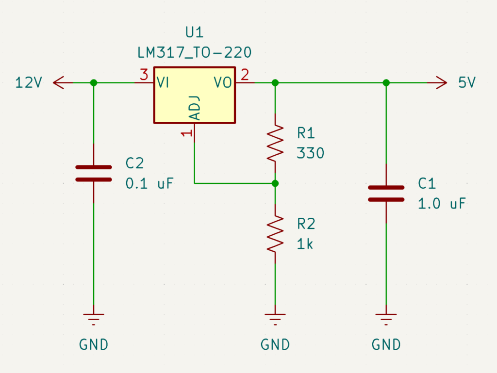
To illustrate the voltage regulation process, let’s construct a simple 5V power supply using the LM317 regulator. Here’s what you’ll need:
- LM317 Voltage Regulator
- 330 Ohm Resistor (R1)
- 1k Ohm Resistor (R2)
- 1 µF Capacitor (C1)
- 0.1µF Capacitor (C2)
- LM317 Datasheet

The LM317 operates as a voltage regulator by adjusting the output voltage based on the ratio of two external resistors, R1 and R2. Referring to the datasheet we find the following formula (See Figure 2):
$$V_O = V_{REF} \left(1 + \frac{R_2}{R_1}\right) + (I_{ADJ} \times R_2)$$

We can see that IADJ in negligible so we can simplify the equation further to (See Figure 2):
$$V_O = V_{REF} \left(1 + \frac{R_2}{R_1}\right)$$
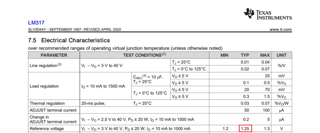
According to the datasheet VREF is between 1.2V and 1.3V with a typical value of 1.25V (See Figure 3). We will assume a value of 1.25V for our purposes. So lets calculate the resistor values we need to achieve a 5V output.

To figure out the resistor values we’ll assume a value for R1 and then solve for R2. The formula to solve for R2 is:
$$R_2 = \frac{(V_O – V_{REF}) \cdot R_1}{V_{REF}}$$
Substitute the values:
$$R_2 = \frac{(5V – 1.25V) \cdot 330}{1.25V}$$
$$R_2 = \frac{3.75V \cdot 330}{1.25V}$$
$$R_2 = 990 \, \Omega$$
Now we understand how to determine the resistors needed to control the output voltage. We can also use a calculator LM317 Calculator to determine the required resistor values.
Assembly and Testing
- Connect the components according to the schematic: connect the input voltage to the LM317’s input pin, the 330 Ohm resistor between the output and adjust pins, and the 990 Ohm resistor between the adjust pin and ground. Place the 1 µF capacitor on the input and the 0.1 µF capacitor on the output for stabilization.
- Test the output voltage with a multimeter to ensure it is stable at 5V. If necessary, fine-tune the resistors to achieve the desired output.
Conclusion
Building a stable 5V power supply using the LM317 voltage regulator is straightforward and effective for automotive and other electronics applications. Understanding and implementing proper voltage regulation ensures your electronic devices receive a consistent and reliable power supply, minimizing the risk of malfunction due to power fluctuations.
By following these steps, you can confidently design and build power supplies tailored to your specific needs, leveraging the versatility and reliability of the LM317